We’ve covered some basics on NCL (signals and gates), next I’m looking into registers and structuring a system with multiple components.
Theory
In synchronous logic, designers use flip-flops to store data, they store the current value on every clock edge, moving it to the next stage. In asynchronous logic, there is no clock edge, so saving data requires something else. NCL uses threshold gates as registers, which works because of their hysteresis property. The requirements for the register:
- Hold on to the value for as long as the next module needs it
- Send a reset (NULL) signal to the next module on all inputs when it needs it
- Let the previous register know what it needs (DATA/NULL)
So, there’s handshaking going on here, each register tells the one before it what it needs, and tries to send the next one what it asks for.
Design
How do we send the request to the previous module then? Lets assume 1 control line, and see if we need something else later. Since we are representing NULL with 0, lets set a request for null to be 0, and a request for data to be 1. We want to receive data as soon as the module has reset to NULL, and we want NULL as soon as the module is outputting data on all groups. Here’s the initial design:
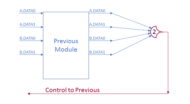
If both A and B have a line set (either 0 or 1) then the ‘watcher’ gate is set. The little circle on the tip is an inverter, it turns the 1 (indicating we have DATA) to a 0 (indicating we want NULL) and vice versa.
There is one more requirement: If the module after us is requesting DATA, we can’t store the NULL wavefront (which would overwrite the DATA values) and vice versa and so need to hold the previous module until we can. This means that the request has to be based on the register’s outputs, not its inputs.
Refresher: A group of NCL lines are the set of lines representing a single entity, only one can be active at a time, but it is allowable to have none active (NULL).
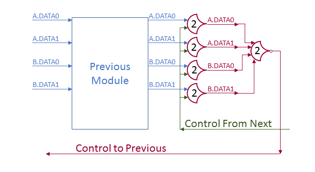
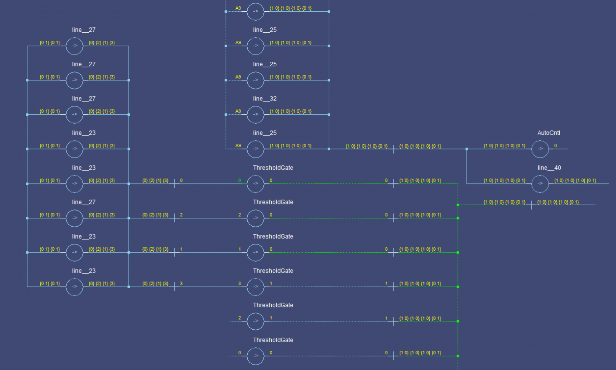
Here we have a gate saving each bit: If the control input is low, then the gates will reset when the previous module’s outputs clear (next module requesting null). If the control input is high, then the gates will save DATA inputs (next module requesting DATA).
When both groups (A and B) have data, the watcher sees 2 data lines, sets its output, which goes through the inverter and requests NULL (which won’t be saved until the next module requests NULL).
Eventually, the previous module NULLs out and waits for a DATA request. When the next module requests NULL, the register gates flip to NULLs and the watcher outputs a 0, which is inverted to a 1 (request for DATA). The NULL wavefront passes through the module to the next register.
This cycle continues.
Notes
Components can be directly linked without registers, but only one operation can occur between registers at a time. Adding the registers splits up the operation into smaller parts, which can occur in parallel (for different inputs). At the start, the first set of inputs is loaded, and when they move to the second stage, the first is NULLed, after that, the first stage receives the second set of inputs, while the first set is still running through the third stage. this continues, with all data wavefronts separated by NULL wavefronts.
2 Replies to “NCL Register Design”