Theory
The decoder is like a backwards multiplexer, it uses the selector bits to output a DATA 1 on a single output, and DATA 0 on the others. This can be used to enable one of many modules, or just to change encoding from binary to one-hot.
Design
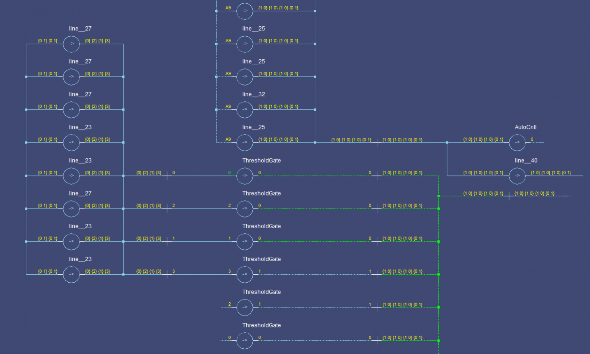
If you remember how we made the MUX module, we had a loop that generated a set of selector lines (DATA0 or DATA1 from each selector input) for each case. We will re-use this, but we will generate a TRUE and FALSE signal for each case (DATA0 and DATA1 of the corresponding output). The TRUE gate for each case will be a THNN, and the FALSE gate will be a TH1N. Here is what a Decoder2 module would look like:
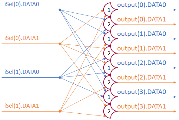
The inputs to the TH1N gates (FALSE) are the opposing rails to the THNN gate of the same case.
CaseTrue='All bits for this case set'CaseFalse='Any other bit set'
Any NULL input produces some NULL output: The THNN gates (TRUE) can’t set because they will always be missing an input, and for any particular input (missing a bit) there are two possible outputs: one with the bit set and one with it clear; these FALSE outputs will remain off as they need the DATA0 and DATA1 respectively from the missing input.
The decoder is actually a fairly simple gate. It is possible to split the DMUX into two parts: DMUX1, and DMUX0. These components would output the DATA1 and DATA0 lines respectively. They are not valid as complete NCL components, but they are useful: You can make a MUX by using a DMUX1 and 2*NumOptions TH22 gates. This might be especially useful when making a MUX that takes in multi-bit options. A single DMUX1 would be used to generate the control signals, and each signal of each bit of each option would be gated with the TH22 gates.
One Reply to “NCL Decoder Design”