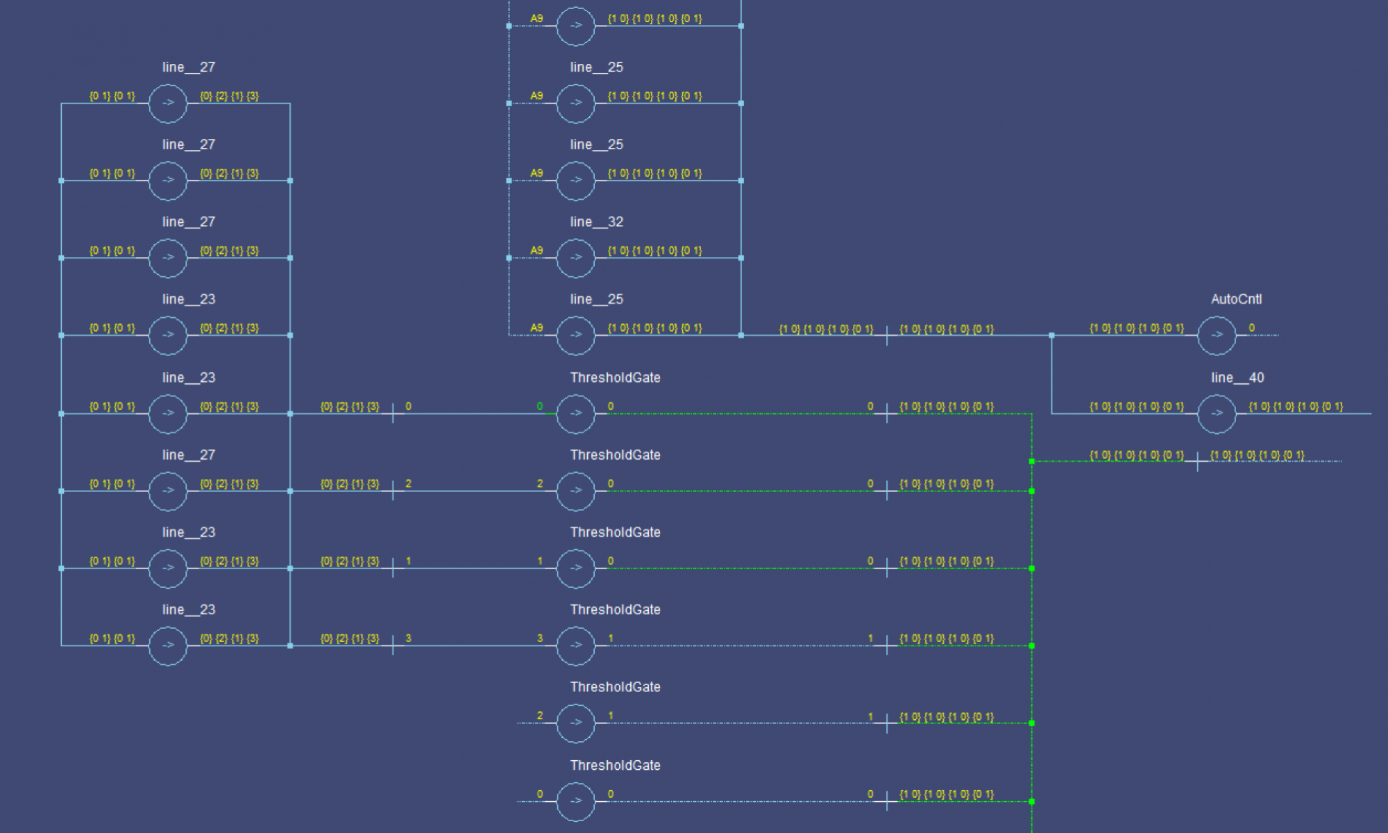
In this post, we built a ring of registers and set a data wavefront loose in it. We added many stages, and watched the single wavefront run through them. In this post, I’ll show what happens with multiple wavefronts.
Theory
First, we should establish how many registers we need for some number of wavefronts. From the Register Ring post, we know that in order for a state (DATA or NULL) to pass on, the next two stages must both be in the opposite state. This prevents the passage from overwriting the next stage’s state completely, as it has already passed on to the next stage.
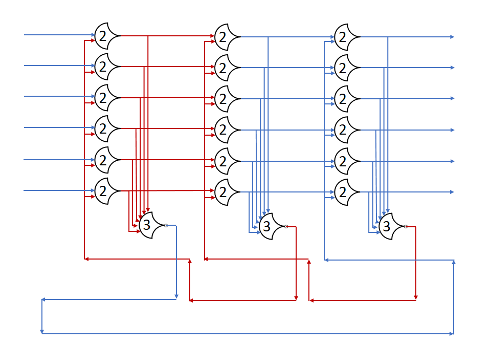
Here, the DATA state (red) can move on to the next stage because the NULL state has been passed up to the 3rd stage. By overwriting the 2nd stage, no state is lost, because stage 2 has already finished with the NULL state.
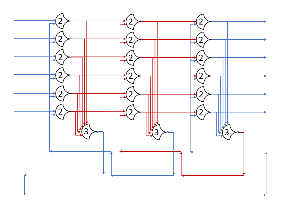
Here, stage 2 cannot pass DATA on to stage 3 because that would remove the NULL state entirely. If there were 4 stages, and the 4th was NULL, then the 3rd stage could accept data, since the NULL state would be preserved.
As you can see, the number of stages in a state is not important, but rather the sequence must be preserved. Let’s assume a really long line of registers for a moment, with stage states: (DATA, NULL, NULL, DATA, ...) All of these NULLs can be assumed to be the same logical state, which we’ll refer to as NULL1, we’ll also call the first DATA state DATA1: (DATA1, NULL1, NULL1, DATA0, ...). Take the case where the last DATA wave can’t move because of some really slow stage after it. If we ‘run’ the system for a register delay, the DATA1 state progresses, and overwrites one of the NULL1 states, but there are still some left, so nothing is really lost. When DATA1 moves forward, a NULL state fills its stage; this is a new state, so let’s call it NULL2: (NULL2, DATA1, NULL1, DATA0, ...). If we run again, one might expect the DATA1 state to advance again, but taht would overwrite the NULL1 state completely, putting two distinct DATA states right next to each other. Having two adjacent DATA states prevents the components from resetting between them, which only produces correct results if the DATA states are identical. Since there is no guarantee that DATA1 and DATA0 are identical, we have to preserve the NULL between them.
There are states which would be deadlocked, however, as long as the initial conditions are valid (not deadlocked), the handshaking ensures that these states never occur as a propagation of the circuit.
Some examples:
- Ring:
(NULL, DATA, NULL, DATA)(4 states) – Nothing can pass, the system is deadlocked (we can’t actually get here naturally) - Ring:
(NULL, DATA, NULL, NULL)(2 states) – Only the DATA state can pass, the NULLs are contiguous, so they can be considered to be identical states - Ring:
(NULL, DATA, DATA, NULL)(2 states) – Both states can pass, the DATA can overwrite the NULL in position 4, and the NULL can overwrite the DATA in position 2 - Ring:
(NULL, DATA, DATA, DATA)(2 states) – Only NULL can pass, if DATA was able to pass, the NULL could be deleted from the system - Ring:
(NULL, NULL, DATA, NULL)(2 states) – Only DATA can pass, if NULL was able to pass, the DATA could be deleted from the system - Rotations of these work out to the same thing since it’s a ring
Note that DATA and NULL are symmetric and the values in the DATA wave don’t matter. You can swap instances of ‘NULL’ and ‘DATA’ and get a valid result.
In short, with an even number of stages, you can only have N/2 states. What about odd numbers?
- Ring:
(NULL, DATA, NULL, NULL, DATA)(4 states) – Only the first DATA can move, as it is the only stage followed by 2 of the opposite state - Ring:
(NULL, DATA, DATA, NULL, DATA)(4 states) – Only the first NULL can move, as it is the only stage followed by 2 of the opposite state
Remember that rotations still match
- Ring:
(NULL, DATA, NULL, NULL, NULL)(2 states) – Only the first DATA can move, as it is the only stage followed by 2 of the opposite state - Ring:
(NULL, DATA, DATA, NULL, NULL)(2 states) – Either state can move- Ring:
(NULL, DATA, DATA, DATA, NULL)(2 states) – Either state can still move - Ring:
(NULL, NULL, DATA, NULL, NULL)(2 states) – Only DATA can move
- Ring:
In the odd case, we can get up to (N+1)/2 states to fit. One thing to note is that when the pipeline is full (max number of states) only one state can move at a time in the odd case. In the even case, there’s that extra space that doesn’t get us another state, but it does give the states some wiggle room: more than one state can be advancing at a time.
From the above, we get: NumStages=NumStates+Advancement where Advancement is the maximum number of states that can advance at a time. Advancement must be greater than 0, if it equals 0, the pipeline will be locked. If Advancement>=NumStates then there’s no real advantage to adding more stages, unless the stages are not delay-matched.
Note: NumStates is always even in a ring.
Experiment
We’ll start with a full pipeline (Advancement=1) and then try a throughput-optimized design (Advancement=NumStates) where every state can advance simultaneously. By using the same number of states, we can benchmark the throughput and latency of the two.
Lest use NumStates:=4, which corresponds to 2 NULL and 2 DATA states.
Minimized Pipeline
By our formula above, we need 4+1=5 stages. The initial state:
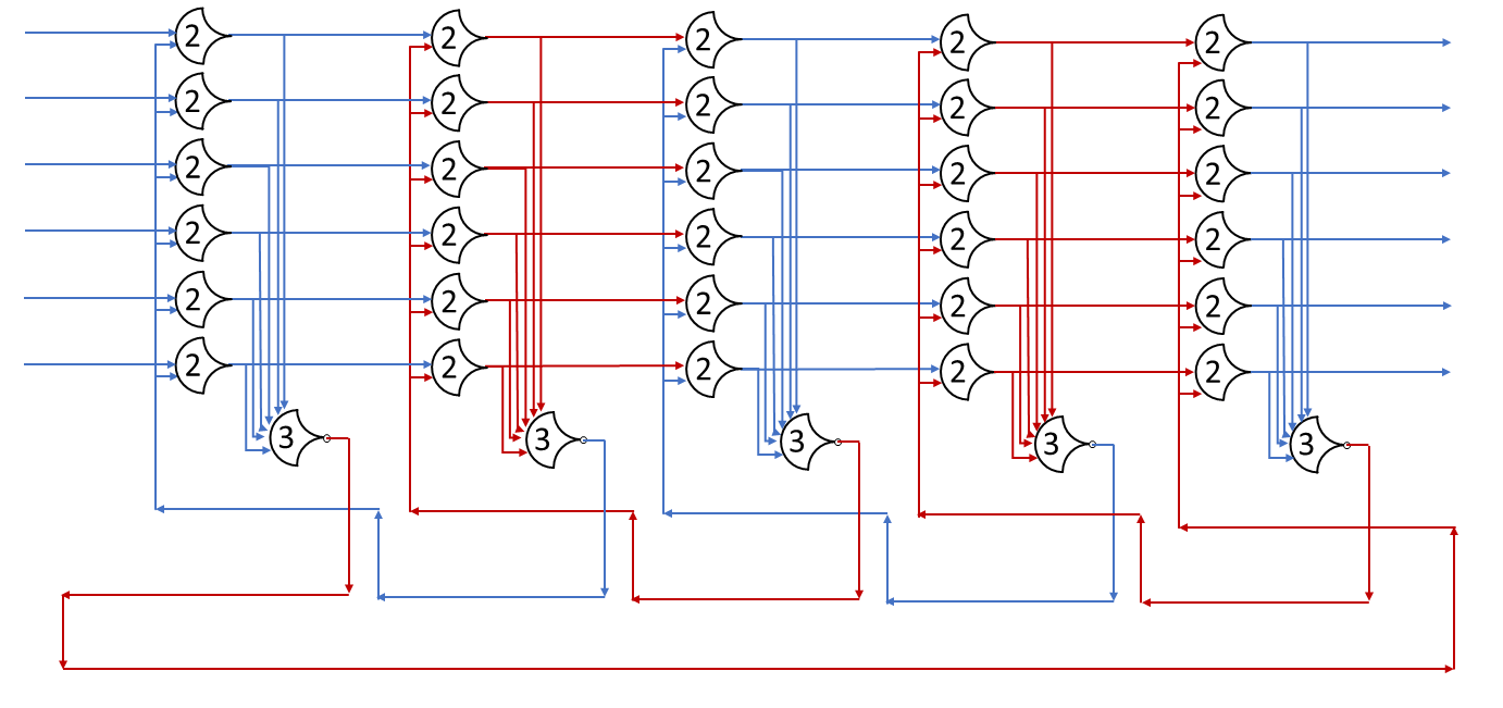
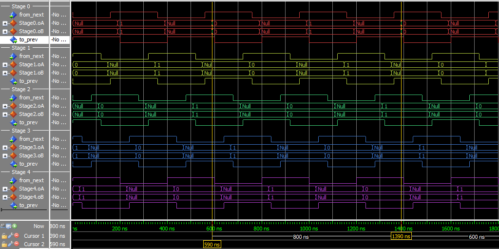
By putting the value of 0 in the first DATA state, and 1 in the second state, we can track when the ring completes a cycle. Throughput is 2/t_complete (two DATA states per trip around the ring) and latency is t_complete.
- Throughput:
1/(400 ns) = 2.5 MHz - Latency:
800 ns
This experiment used the static_loop VHDL file, and a specific test script.
Throughput-Optimized Pipeline
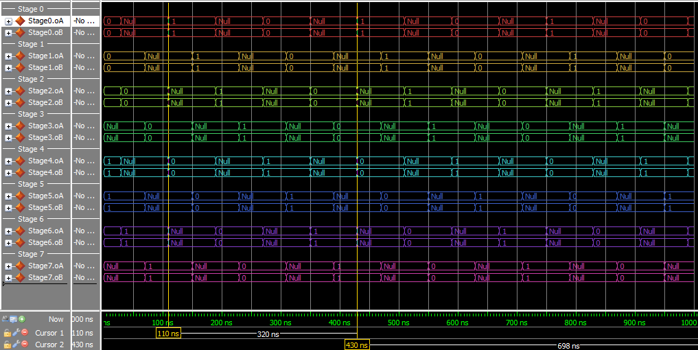
This version has 4+4=8 stages to go through, but all the states can move at the same time. Throughput should increase, but latency may increase as well. I’m not going to show the diagram because of size problems, but it’s a lot like the above, just with more stages.
Throughput and latency are calculated from the simulation, just as before. For optimal throughput and startup latency, arrange the states in pairs – 2 DATA, then 2 NULL, then 2 DATA, … – this increases the number of Advancement options at the start to the maximum: NumStates.
- Throughput:
1/(160 ns) = 6.25 MHz - Latency:
320 ns
This experiment used the static_loop VHDL file, and a specific test script.
Results
It looks like the throughput-optimized pipeline indeed has a higher throughput: By adding 3 states, we were able to more than double the efficiency of the ring, if you look at the simulation waveforms, in the first one only one stage is transitioning at a time. In the second, 4 stages are transitioning at a time. The second (faster) version uses 8/5 the resources though, so the decision on how many stages to use depends on available die space as well. In simulation, we don’t have to worry about this.
