Theory
A Shifter takes an array of bits, and shifts them right of left. Numerically, this is like multiplying or dividing by 2 (in the case of binary numbers). Some examples:
| Direction | Input | Shift Amount | Output |
|---|---|---|---|
| Right | 001001 |
1 | 000100 |
| Left | 001001 |
1 | 010010 |
| Right | 001001 |
2 | 000010 |
| Left | 001001 |
3 | 001000 |
This could be applied to non-binary variables as well (like 3-rail signals) but the exact meaning will be different. There are a few ‘extensions’ to this behavior I’d like to add:
- Rotation
- Arithmetic shifting
Rotation allows the bits shifted out one end to be shifted back in the other:
| Direction | Input | Output |
|---|---|---|
| Right | 1001 |
1100 |
| Left | 1001 |
0011 |
Arithmetic shifting treats the shift as a mathematical operation and preserves the sign of the number. It is only valid for right shifts.
| Direction | Input | Output |
|---|---|---|
| Right | 100(-4) |
110(-2) |
| Right | 110(-2) |
111(-1) |
The sign of a number is represented by leading 1’s in the MSB, so an arithmetic right shift adds 1’s into the leftmost bits, if the number was negative. This is accomplished by shifting in the MSB.
Design
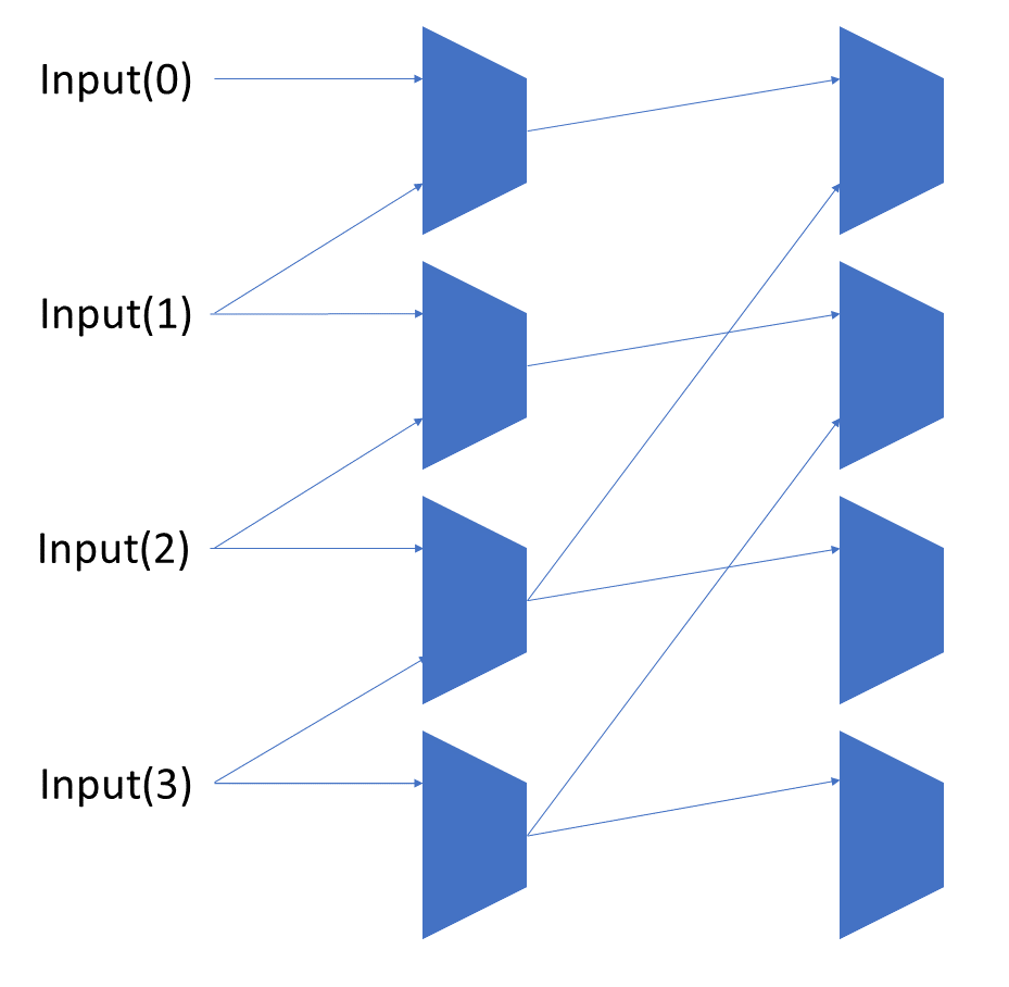
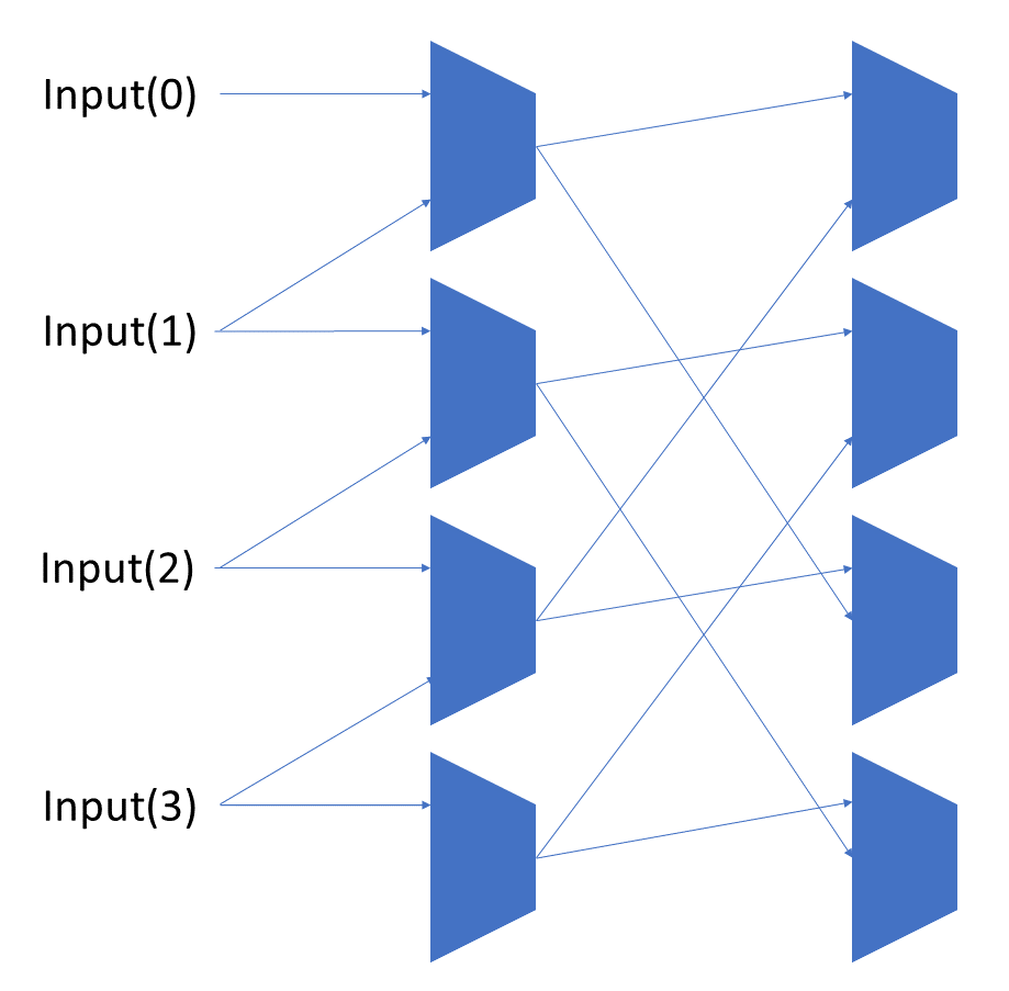
Each shift_amount bit corresponds to a shift of 2^n, where n is the index of the bit. Each constant-size shift can be accomplished with only wiring. As my CprE 381 professor always said, if you have two possible values, the easiest way to pick one is a MUX. So, each shift_amount bit will choose between an unshifted, or 2^n shifted value. By connecting these in layers, we get a shift of any size.

The un-supplied inputs are 0’s. The first column is controlled by shift_amount(0), the second column is controlled by shift_amount(1).
To change the direction, we add a mux at the beginning that selects a reversed version of the input, let the shifter shift that, then un-reverse it at the end.
To add rotations, we add another input to the MUX’s at the bottom that feeds back from the top, so that the ‘lost’ bits are shifted back in.

To add arithmetic operations, the unassigned inputs in the lower MUX’s are changed from 0 to the MSB of the input. This signal is constant across all the MUX’s it is applied to, so it is generated with a single MUX. On a left shift, the shifted-in value must be 0, so the MUX can only output the MSB when a right arithmetic shift is selected.
Implementation
the VHDL source, using generics to make it work for any number of inputs (even non-powers of 2, btw):
library ieee;
use work.ncl.all;
use ieee.std_logic_1164.all;

entity Shifter is
  generic(NumInputs : integer := 2);
  port(inputs       : in ncl_pair_vector(0 to NumInputs - 1);
       shift_amount : in ncl_pair_vector(0 to clog2(NumInputs) - 1);
       direction    : in ncl_pair;
       rotate       : in ncl_pair;
       logical      : in ncl_pair;
       output       : out ncl_pair_vector(0 to NumInputs - 1));
end Shifter;

architecture structural of Shifter is
  constant NumShiftAmountBits : integer := clog2(NumInputs);
  constant NumRows : integer := clog2(NumInputs);

  type RowSignals is array (integer range <>) of ncl_pair_vector(0 to NumInputs - 1);

  -- The shifted array at each stage of the shifter.
  signal rows : RowSignals(0 to NumRows);

  -- A generated value that is always DATA0 or NULL as appropriate
  signal zero_in : ncl_pair;

  -- The third input that is used for either logical or arithmetic operations.
  signal non_rotate_in : ncl_pair;

  signal input_reversed : ncl_pair_vector(0 to NumInputs - 1);
  signal output_reversed : ncl_pair_vector(0 to NumInputs - 1);

begin

  produceDATA0: THmn
    generic map(M => 1, N => 2)
    port map(inputs(0) => inputs(0).DATA0,
             inputs(1) => inputs(0).DATA1,
             output => zero_in.DATA0);

  zero_in.DATA1 <= '0';   msb_in_mux: MUX     generic map(NumInputs => 4)
    port map(iOptions(0) => inputs(NumInputs-1),
             iOptions(1) => zero_in,
             iOptions(2) => zero_in,
             iOptions(3) => zero_in,
             iSel(0) => logical,
             iSel(1) => direction,
             output => non_rotate_in);

  in_bit_flipper: for i in 0 to NumInputs-1 generate
    input_reversed(i) <= inputs(NumInputs-1-i);     directionMux: MUX       generic map(NumInputs => 2)
      port map(iOptions(0) => inputs(i),
               iOptions(1) => input_reversed(i),
               iSel(0) => direction,
               output => rows(0)(i));
  end generate;

--  rows(0) <= inputs;

  rowsloop: for r in 0 to NumRows-1 generate
    columns: for c in 0 to NumInputs-1 generate
      ifstd: if (c + (2**r)) < NumInputs generate         multiplexer: MUX           generic map(NumInputs => 2)
          port map(iOptions(0) => rows(r)(c),
                   iOptions(1) => rows(r)(c + (2**r)),
                   iSel(0) => shift_amount(r),
                   output => rows(r+1)(c));

      end generate;

      ifwrp: if (c + (2**r)) >= NumInputs generate
        multiplexer: MUX
          generic map(NumInputs => 4)
          port map(iOptions(0) => rows(r)(c),
                   iOptions(1) => non_rotate_in,
                   iOptions(2) => rows(r)(c),
                   iOptions(3) => rows(r)((c+(2**r)) mod NumInputs),
                   iSel(0) => shift_amount(r),
                   iSel(1) => rotate,
                   output => rows(r+1)(c));

      end generate;
    end generate;
  end generate;

  out_bit_flipper: for i in 0 to NumInputs-1 generate
    output_reversed(i) <= rows(NumRows)(NumInputs - 1 - i);     outMux: MUX       generic map(NumInputs => 2)
      port map(iOptions(0) => rows(NumRows)(i),
               iOptions(1) => output_reversed(i),
               iSel(0) => direction,
               output => output(i));
  end generate;

end structural;
This code generates the necessary multiplexers for shifting the signal, flipping it at the input and output, and selecting how to handle the bits that can’t be shifted normally (because the source is out of range).
Testing
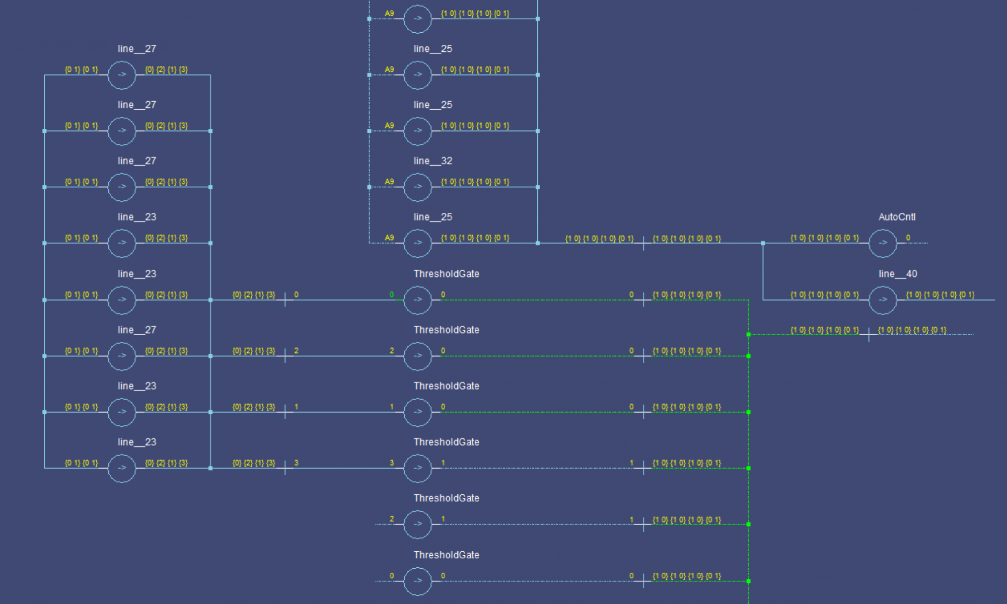
I made a simple test script to run through some cases. Everything seems to check out, here’s a sample:


