After several hours of getting oscillatory behavior from the register ring with the resets tied to switches, I decided to try a different approach. I had been avoiding using the processing system in the design because I was working at a bench and I assumed that it would be simpler to only deal with the hardware. As part of a class at my university, I was setting up a set of remote-access systems for FPGA development, and I thought I’d try something interesting.
By using a GPIO in the design, I was able to avoid switch bouncing entirely, which seems to have helped. I built a 4-stage ring with a shared reset and an input to force a DATA0 or DATA1 out of one stage (OR with the corresponding signal between the registers).
The GPIO was connected to these 3 control signals, and the outputs of each stage (8 inputs). Setting the reset should bring all 4 registers to NULL, and forcing a DATA value should cause it to propagate to all but one register. The first register to receive that data signal will transition to requesting NULL, and therefore the register before it (the one who’s outputs are being overridden) will remain at null. Once the force_data# line is cleared, register 2 receives NULL and requests data, and so on as the wavefronts cycle.
For more information on register rings, see this post.
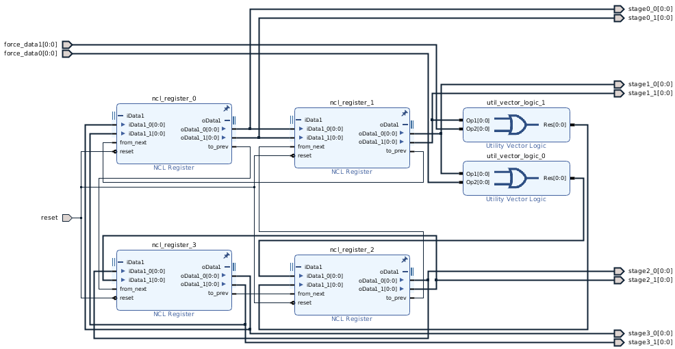
The synchronous portion of the design interfaces to this using a GPIO module on a 100 MHz clock. This is almost certainly slower than the NCL portion of the design will operate, but by carefully measuring the system under reset states, or while a force_data# line is active, certain conditions can be tested. The synchronous part of the design has a lot of platform-specific blocks, but can be simplified to a processor connected to a General-Purpose Input-Output module. The code I used to test the module from the processor is given below (the struct is just used as a way to name bits in the GPIO’s registers).
struct gpio_pins {
    union {
        struct {
            u8 s00 :1;
            u8 s01 :1;
            u8 s10 :1;
            u8 s11 :1;
            u8 s20 :1;
            u8 s21 :1;
            u8 s30 :1;
            u8 s31 :1;
            u32 :24;
        };
        u32 values;
    };
    u32 :32;
    struct {
        u8 rst :1;
        u8 force_data0 :1;
        u8 force_data1 :1;
        u32 :29;
    };
};

int main() {
    // Make a pointer to the pins, using the bitfield to interpret them.
    volatile struct gpio_pins* pins =
            (volatile struct gpio_pins*) (XPAR_AXI_GPIO_0_BASEADDR);
    struct gpio_pins reading0 = *pins;
    pins->force_data0 = 0;
    pins->force_data1 = 0;
    pins->rst = 1;
    struct gpio_pins reading1 = *pins;
    pins->rst = 0;
    struct gpio_pins reading2 = *pins;
    struct gpio_pins reading3 = *pins;
    int a;
    for (a = 0; a < 100; a++) {
        reading3.values |= pins->values;
    }
    if (reading3.values) {
        while (1)
            ;
    }
    pins->force_data0 = 1;
    struct gpio_pins reading4 = *pins;
    for (a = 0; a < 100; a++) {
        if (pins->values != 0x51) {
            while (1)
                ;
        }
    }
    pins->rst = 1;
    pins->force_data0 = 0;
    pins->force_data1 = 1;
    pins->rst = 0;
    struct gpio_pins reading5 = *pins;
    for (a = 0; a < 100; a++) {
        if (pins->values != 0xA2) {
            while (1)
                ;
        }
    }
    pins->force_data1 = 0;
    for (a = 0; a < 1000000; a++) {
        // DATA0 lines should not get set
        if ((pins->values &0x55)) {
            while (1)
                ;
        }
        // at least one DATA1 line should be set
        if ((pins->values &0xAA) == 0) {
            while (1)
                ;
        }
        // at least one DATA1 line should not be set
        if ((pins->values & 0xAA) == 0xAA) {
            while (1)
                ;
        }
    }
    pins->rst = 1;
    pins->force_data0 = 1;
    pins->rst = 0;
    pins->force_data0 = 0;
    for (a = 0; a < 1000000; a++) {
        // DATA1 lines should not get set
        if ((pins->values & 0xAA)) {
            while (1)
                ;
        }
        // at least one DATA0 line should be set
        if ((pins->values &0x55) == 0) {
            while (1)
                ;
        }
        // at least one DATA0 line should not be set
        if ((pins->values & 0x55) == 0x55) {
            while (1)
                ;
        }
    }
    pins->rst = 1;
    return 0;
}
The application first runs static tests, checking that when in reset, all stages output 0 and that when a data value is forced, then the data propagates, but does not fill the ring entirely. The last two loops are testing for the dynamic behavior of the ring. I couldn’t hope to actually measure movement of the waves, so just check that at any given time it is in a valid state, when DATA0 was forced, then no DATA1 lines were asserted and vice versa, and that there was a DATA wave and a NULL wave at all times (as measured). The loops take a couple seconds to run, so I feel confident that any errors would have been caught. I put breakpoints in the while (1) loops, which were not hit, and the breakpoint at the last pins->rst = 1; line always ran. Also if a wave ever disappeared, it shouldn’t have ever come back, so I’m confident that this worked as I wanted it to.
Manual inspection of the values (at low frequency using the debugger reading the GPIO pins) showed that the DATA0/DATA1 lines were behaving as expected as well.
What’s next? I want to do the same experiment with multiple data wavefronts (at least 5 stages) and then start building some simple state machines. After that, I want to look at methods of introducing timing into the system by using a clock or GPIO enable as a data input, with a TH22 gate used to wait for the input to match the wavefront.