Theory
Multiplexers are components that let you switch between different options for a signal. They take in some number of option values (usually a power of 2) and a selector. Each data value of the selector corresponds to a particular input, which is fed to the output.
output = iOptions(iSelector)
If there are 2 options (the most basic MUX) then the selector is 1 bit. If there are 3 or 4 options 2 bits are needed, and so on.
Design
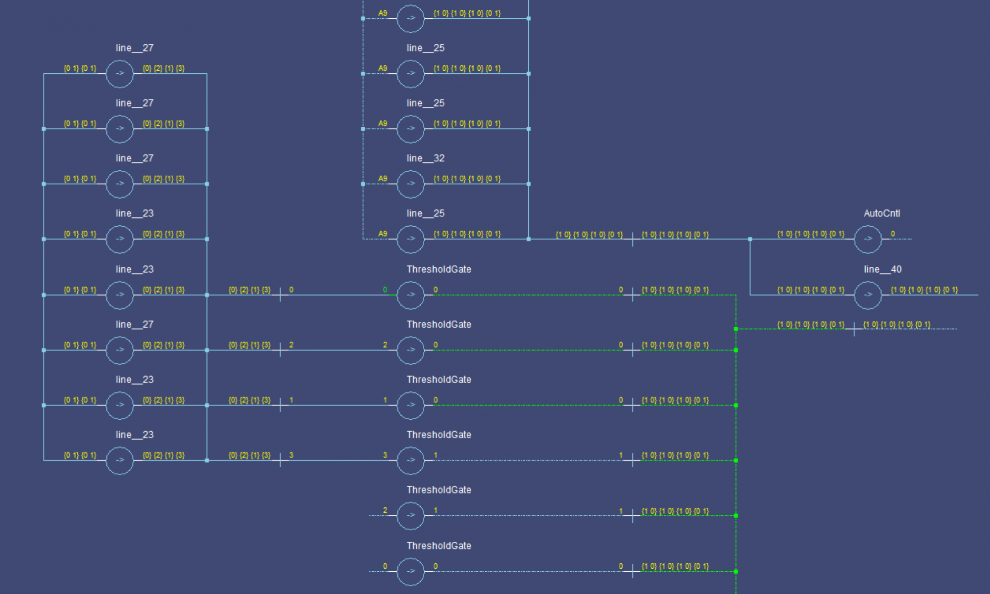
This time we’re going to go about this in a more intuitive, less rigorous, manner. Let’s consider each ‘row’ separately, each row will correspond to one input option (both *.0 and *.1). For each of these rows, we’ll generate a gating signal from the iSelector bits. This gating signal will be used by two TH22 gates to clear all but the selected signals.
This is very much like having 2 MUXes, one for the *.1s and one for the *.0‘s.
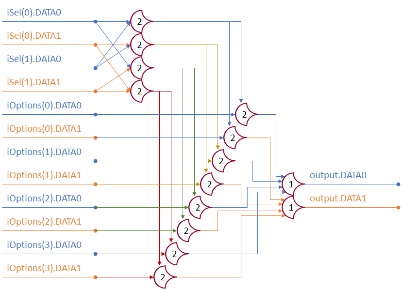
We’ll be reusing some code from the FullAdder implementation to get the selectors (one wire per input case); each of these will gate the DATA0 and DATA1 lines of the respective input option. The gated values will then be combined with a TH1n gate. An example 4-option case:
Case0 <= TH22(iSel(0).DATA0, iSel(1).DATA0)
Case1 <= TH22(iSel(0).DATA1, iSel(1).DATA0)
Case2 <= TH22(iSel(0).DATA0, iSel(1).DATA1)
Case3 <= TH22(iSel(0).DATA1, iSel(1).DATA1)

GatedA0 <= TH22(iOptions(0).DATA0, Case0)
GatedA1 <= TH22(iOptions(0).DATA1, Case0)

GatedB0 <= TH22(iOptions(1).DATA0, Case1)
GatedB1 <= TH22(iOptions(1).DATA1, Case1)

GatedC0 <= TH22(iOptions(2).DATA0, Case2)
GatedC1 <= TH22(iOptions(2).DATA1, Case2)

GatedD0 <= TH22(iOptions(3).DATA0, Case3)
GatedD1 <= TH22(iOptions(3).DATA1, Case3)

output.DATA0 <= TH14(GatedA0, GatedB0, GatedC0, GatedD0)
output.DATA1 <= TH14(GatedA1, GatedB1, GatedC1, GatedD1)
That’s a bit repetitive, let’s make it a little more general. The design involves some ‘magic’ parts because they are more of an implementation detail really.
for Case in 0 to N-1
  [build CaseBits with DATA0's and DATA1's]
      -- CaseBits is a concatenated signal from the iSelector input
  Selectors(Case) <= THNN(CaseBits)

  GatedCase0 <= TH22(Selectors(Case), iOptions(Case).DATA0)
  GatedCase1 <= TH22(Selectors(Case), iOptions(Case).DATA1)
next Case

output.DATA0 <= TH1N(Gated00, Gated10, Gated20, Gated30, ...)
output.DATA1 <= TH1N(Gated01, Gated11, Gated21, Gated31, ...)
Each row generates a selector, gates the option values, and passes them to the output. Any un-selected inputs are NULLed out (Gated#0 and GATED#1 both go to 0) leaving only the selected input to pass through the TH1N gates.
2 Replies to “NCL Multiplexer Design”