NCL THxor0 Gate

The THxor0 Gate is a 4-input gate with logic function AB + CD. Data that I have found about implementing this gate is all at the transistor level. For now, I’ll make a behavioral model, but I may later design a structural version (technically a 1-bit state machine). Regardless, I think this implementation is actually synthesizable, so that’s nice

The behavioral implementation:

entity THxor0 is
  generic(Delay : time := 1 ns);
  port(A, B, C, D : in std_logic;
       output : out std_logic);
end THxor0;

architecture behavioral of THxor0 is
begin
  process (A, B, C, D)
  begin
    if (A = '0' and B = '0' and C = '0' and D = '0') then
      output <= '0';
    elsif ((A and B) or (C and D)) = '1' then
      output <= '1';
    end if;
  end process;
end behavioral;

The process statement again has 2 conditions: Set and Clear. If neither is met, the gate holds it’s state.

Testing

The test script was a modified version of the THmn test script. See scripts/test/test_threshold_gate.tcl on GitHub. Below is an excerpt from the test simulation session.

capture1.png

See this post for a Half Adder component that uses this gate.

Commit: 19c8318

NCL Half Adder Design

Definition

A Half Adder is a logic component that takes in two inputs, and outputs a binary (base 2) representation of how many are set (0, 1, or 2).

Like any good logic designer working on a small part, we’ll start by making a truth table:

iA iB oSum oCarry
0 0 0 0
0 1 1 0
1 0 1 0
1 1 0 1

Design

The first step of getting from truth table to gates is to generate Sum-of-Product logic equations, even with NCL.

oSum = (iA*iB')+(iA'*iB)
oCarry = iA*iB

Now begins the difference: We don’t treat iA' the same as we would in standard boolean logic. In standard boolean logic, we get the compliment by inverting the single signal. In NCL, we have to use an entirely different signal. In addition, we need logic functions to generate the compliments of our outputs.

oSum.1 = (iA.1*iB.0)+(iA.0*iB.1)
oSum.0 = (iA.1*iB.1)+(iA.0*iB.0)
oCarry.1 = iA.1*iB.1
oCarry.0 = (iA.0*iB.0)+(iA.1*iB.0)+(iA.0*iB.1)

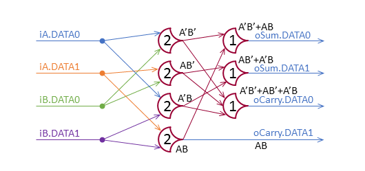
Looking at these functions, it looks like we need 4 2-input gates that each check if both inputs are set (C-Element/TH22), and several gates that check if any inputs are set (OR/TH1n). Lets start by setting up the 4 TH22 gates (the ‘AND plane’):

halfadder-and-plane1.png

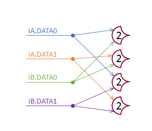
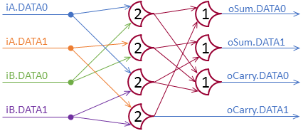
The gates represent iA'*iB', iA*iB', iA'*iB, and iA*iB from top to bottom. For each of these, if both inputs are set (remember that setting iA.Data0 means iA==0) the output is set; if both are clear, the output is clear. Since oCarry is just iA*iB, we can wire that output up directly. The others use multiple pairs, that are OR’ed together: if any one is set, the output line is set. Sounds like a TH1n gate.

HalfAdder

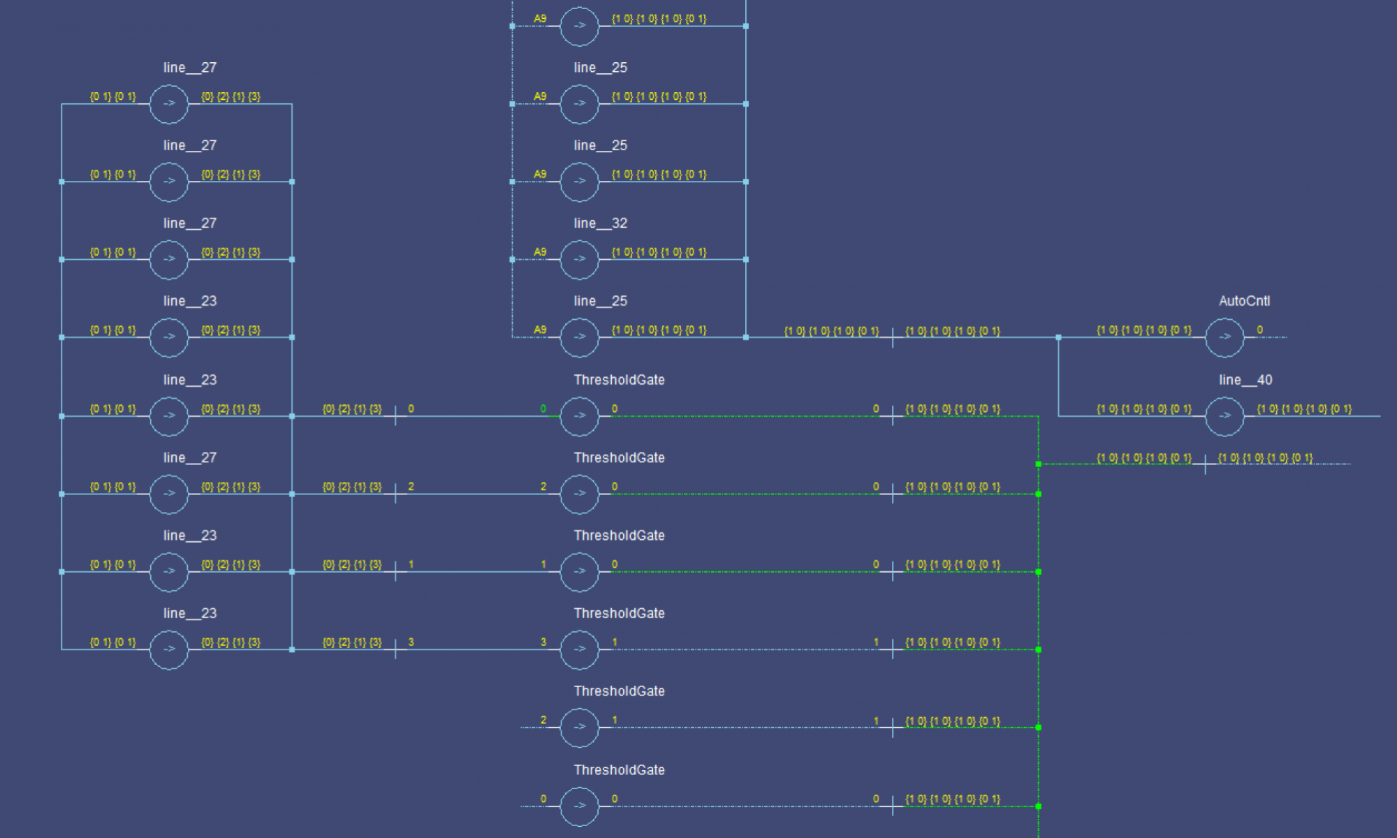
So, that’s the basic Half Adder. I double checked it by annotating the gates to make sure I got the same thing:

halfadder-annotated.png

Looks good. Now, let’s get fancy.

Optimizing

Optimizing NCL functions should be similar to optimizing standard logic functions. I’m going to try to optimize for logic levels, to see if I can make it all flat.

oCarry.0

By observation, we have symmetry between iA and iB, and iA' and iB', Since we don’t want iA*iB to be enough to trip the gate, lets consider weighting iA' and iB' at 2. This gives a THm4W22 gate. Now to figure out m:

  • If iA and iB are set, then the total is 2, so we need to be larger than 2.
  • If any other 2 lines are set, we have ≥3 (either 2+1 or 2+2)

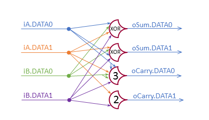
Three it is. We will use oCarry.0 = TH34W22(iA.0, iB.0, iA.1, iB.1)

oSum

Looking through the table here, I don’t see a matching function for the gates I’ve studied, but there is a XOR gate: THxor0. This gate picks out the first two, and last two inputs as an SOP function.

oSum.0 = THxor0(iA', iB', iA, iB)
oSum.1 = THxor0(iA, iB', iA', iB)

Together

HalfAdder Optimized

Implementation

I’ll save this for another post.

Getting Down to Business

Now that we’ve talked about what NCL is, it’s time to actually make something with it.

For complete project files, see my GitHub

I will be using Modelsim as my IDE (with a little Notepad++) and VHDL. I’ll be starting with simulation, but eventually I want to load something on an FPGA, so I’ll be keeping an eye for synthesis where I can.

Setup

The first thing to do is make a package with some useful types and functions. I’ll call it work.NCL:

library ieee;
use ieee.std_logic_1164.all;

package ncl is
  type ncl_pair is record
    data0 : std_logic;
    data1 : std_logic;
  end record ncl_pair;
 
  type ncl_pair_vector is array (integer range <>) of ncl_pair;

  component THmn is
    generic(M : integer := 1;
            N : integer := 1;
            Delay : time := 1 ns);
    port(inputs : in std_logic_vector(0 to N-1);
         output : out std_logic);
  end component THmn;
end ncl;

I’ve decided to make each NCL line be std_logic to allow the synthesizer to use standard logic functions.

The gates themselves operate on single lines, but components take in pairs, though it could be expanded to triples or higher if needed later. Before, we can do anything else we need to build the NCL Threshold gate.

Implementation

I tried to implement the threshold gate structurally with the generic parameter, but I was unable to make it work, I’ll look into making a structural version someday.

For synthesis, I may need to make parameter-specific components. The generic component could maybe act as an automatic selector, instantiating the correct implementations.

The most basic description of a threshold gate is that it sets when enough inputs are set, when no inputs are set, the output clears, otherwise no action is taken. For now, I have decided to implement the threshold gate without weights, and instead to use repeated inputs (handled by the calling entity) if I need weights. A TH23W2 would be instantiated as a TH24, and the first input would be given twice.

Here goes:

library ieee;
use ieee.std_logic_1164.all;

use work.ncl.all;

entity THmn is
  generic(M : integer := 1;
          N : integer := 1;
          Delay : time := 1 ns);
  port(inputs : in std_logic_vector(0 to N-1);
       output : out std_logic := '0');
end THmn;

architecture simple of THmn is
begin
  ThresholdGate: process(inputs)
    variable num_1 : integer;
  begin
    num_1 := 0;
    for i in 0 to N-1 loop
      if inputs(i) = '1' then
        num_1 := num_1 + 1;
      end if;
    end loop;
    if num_1 >= M then
      output <= '1' after Delay;
    elsif num_1 = 0 then
      output <= '0' after Delay;
    end if;
  end process;
end simple;

Essentially, it counts the number of 1’s, and checks for the set and clear conditions.

Testing

I made a test script to help make sure the generics work correctly (and get practice for testing later modules). Part of a test for TH22 is below:

Capture

See scripts/tests/test_threshold_gate.tcl on GitHub for my tests.

I have tested it for up to TH77, beyond that it takes too long to run (runtime is 2n). My test file is designed to test every possible transition of input values, in both the output set and clear states.


Thanks for reading. If you have any thoughts on how to improve the design, let me know by message or in the comments.

Commit: 5b852e5

The Logo

I want to explain the logo a bit:

Logo

It’s three relevant logic gates in one. The red portion is a Threshold Gate:

cropped-global-diagrams.png

Threshold gates are used by NCL logic. The next gate is the blue one, you may recognize it as an AND gate. Some models of Asynchronous Logic use something called a C-Element, which is drawn like an AND-gate, but it has a ‘C’ in the middle (not shown in the logo). C-Elements are functionally identical to a TH22 gate.

AND_C

The white portion in the middle was not actually something I planned, but I was quite pleased when I noticed the shape. It is the shape of an NCL Threshold gate without hysteresis. These gates aren’t (to my knowledge) used directly very often in designs, but they are the blocks that Threshold Gates with hysteresis are built on.

This is done by feeding the output back to the input m-1 times on an (n+m-1)-input non-hysteresis gate with the same m (see this post).

Threshold_without_Hysteresis

And of course I tried to make it all look sorta cool. Though I admit, it might be too complex for the 16×16 browser tab icon.

If you want, I can provide the GIMP project on GitHub. If you have suggestions for improvements, let me know.

Handshaking & Pipelining

Generally speaking (in this context), handshaking is the process of electronic systems agreeing on what to do next. In NCL, this takes the form of modules requesting a NULL or DATA signal.

  • The request for NULL indicates that the operation has been performed, and the results saved for the next module to use.
  • The request for DATA indicates that the module has reset, passed the reset signal to the next module, and is ready for more work.

If you’re having trouble, think of it like two people doing laundry, one is operating the washing machine, the other is operating the dryer. Additionally, assume that the operators can’t be sure of how long a load will take in either stage. It’s not a perfect analogy, but it might help. Initially, both are empty:

  1. In the empty state, the washing machine operator knows he or she needs clothes, so he or she finds some and puts them in the wash. The drier is also empty, but it needs to get its clothes from the washer, so it has to wait.
  2. When the washer is finished, the operator takes out the clothes and pus them between the washer and dryer, for the dryer’s operator to use when ready. Since the washer is now ‘reset’, it is ready for clothes again, its operator loads it.
  3. The dryer operator sees the clothes are ready to be dried and puts them in the dryer. Eventually they finish and leave the system.

Now, imagine that after a few loads, the dryer can’t keep up, and the washing machine finishes a load while the dryer is still running. The load goes into the space between the washer and dryer. Since the washer can’t know how close the dryer is to completion, it has to wait for the dryer to finish and take the waiting load before starting another.

Null Convention Logic Gates

See this post for information about NCL signals.

Symbol

It may or may not surprise you to know that NCL has it’s own set of gates for building circuits. They are called threshold gates and are drawn as

cropped-global-diagrams.png

with the ‘threshold number’ in the middle. The inputs come in on the left (round) part, and the output comes out the point on the right.

Operation

For all threshold gates:

  • If all inputs are 0, the output is 0
  • If the number of inputs that are set is >= the threshold number, the output is 1
  • Otherwise, it holds its value.

threshold gates can have input weights, meaning that an input can count towards the threshold count more than once.

Notation

A threshold gate is denoted as THmn where m is the threshold value (the number of inputs needed to transition to a 1) and n is the total number of inputs. If weights are needed, then THmnW## is used, where the #’s are replaced with the weights (order is irrelevant). A TH23W2 gate sets when the first input is set (as it is counted twice), or when both of the other 2 are set. The boolean logic function is

TH23W2 Set: A+BC

Note that when just B or C are set, the gate keeps its value, so if it was a 1, then it will stay a 1, and if it was a 0 it will stay a 0. The logic function for clearing the gates is essentially the same for all:

THm1 Clear: A'
THm2 Clear: A'B'
THm3 Clear: A'B'C'
THm4 Clear: A'B'C'D

Summary

Threshold gates are used in NCL because they are less volatile than standard gates. Once they have an output, they hold on to int until their inputs are completely cleared (circuit reset). This means that a NCL component’s output will not flip more than once in an operation. This property of threshold gates means that if the outputs are set, the component has completed, and if they are reset, it has cleared. You always know when it is ready to move on.

Null Convention Logic Signals

If you don’t yet know what asynchronous logic is, I recommend reading this post (or using Google).

For the time being, I will be focusing my efforts on Null Convention Logic (NCL). NCL is technically a separate logic system from boolean logic. For now, I’ll stick to considering it in the context of a boolean system. What that means is that all signals in the design will still be boolean, they will just represent something a little different.

In NCL, each signal (boolean value) still has 2 meanings, but they are changed. A value of 0 means NO_DATA/NULL and a value of 1 means DATA. Different signals have different Data assigned. To represent a standard boolean variable, 2 lines are needed, the encoding:

  • FALSE (0): DATA0=1, DATA1=0
  • TRUE (1): DATA0=0, DATA1=1
  • Null/Unknown: DATA0=0, DATA1=0

The new state, NULL is used when the circuit hasn’t determined a value for the line yet. Detecting completion of the circuit is then as simple as seeing if one line in each group is set. When all the outputs are assigned a value, the values are saved, and the circuit resets to NULL outputs.

Note, it is entirely possible to have more than two lines in a group. Imagine If I made a circuit that took in an 8-bit color value and outputted if it was mostly one of {Red, Green, Blue}. Instead of having 2 boolean variables for 3 states (wasting a combination), I can have 1 three-state variable: {DATA_RED, DATA_BLUE, DATA_GREEN}. When the circuit is reset, the output is unknown, so all three go to NULL, when the inputs are received and the result found, the circuit sets one of the lines. This is not that different from ‘one-hot’ encoding in synchronous logic, except that it does have a defined all-off state that carries meaning (not data, but it does indicate circuit state). In synchronous logic, such a state would be an error.

The most common encodings I’ve come across so far are 2-rail {DATA0 and DATA1} and 4-rail {DATA0, DATA1, DATA2, DATA3}, representing 1 and 2 boolean variables respectively.

Anyways, that’s the basics of NCL signaling. The thing to remember is that the signals have to go to NULL between calculations, otherwise, there’s no way to know when they are ready.

What is Asynchronous Logic?

So, what even is this blog? Well, I want to record my efforts to understand asynchronous (clockless) logic, and help others who may endeavor to do the same. So, what does asynchronous mean?

Well, in ‘traditional’ logic designs, the system uses a clock to synchronize data. In order for data to be saved and made available to the next unit, a clock edge is sent to the registers. This is needed because the signals take time to settle, and that time isn’t constant. This means that the data can’t be saved until enough time has passed to be sure everything is ready.

In Asynchronous Logic, there is no clock. Instead of waiting for enough time to have passed for the signals to be settled, the circuit is aware of when it is ready. There are several ways to accomplish this:

  • Matched Delays: The circuit is designed with a completion signal that is delayed from the inputs. The signal is used to inform the next module that the data is ready. Each module can define it’s own delay, instead of a system-wide clock period.
  • Completion Detection: Since the transistors will continue to consume power until they are done switching, it is possible to measure the current drawn, and signal completion when it drops below a certain threshold.
  • Null Convention Logic: NCL uses a different data encoding scheme to tell when data is finished. Each line is DATA or Null, so a boolean signal is represented by 2 lines (DATA0 and DATA1).

The common element of all of these is that the components/modules have to let the the next module when they are done, and the previous module when they are ready for more data. This is called handshaking. Each stage has to wait for the next to be ready for new data, and for the previous to have new data ready.

Recap:

  • Synchronous Logic requires a clock to tell it when it is ready to do the next thing.
  • Asynchronous Logic is designed to know when it is done internally, removing the need for a clock.

So, asynchronous sounds better, right? It can run at the best speed of the hardware, it doesn’t spend as much power on the clock, etc. The downside that has stood in it’s way up to this point has been that it is harder to design. However, as designs get smaller and faster, the advantages of asynchronous logic become more important.

Introduction

Hey there, everyone. I am going to be posting my experiences here as I work through my asynchronous logic design projects. I’m a Computer Engineering undergrad student at Iowa State University. I will try to answer any questions as much as I can, but this is my first try at asynchronous designs, so I won’t have all the answers.

Anyways, thank you for taking a look and I hope you learn something. If you have a request for something, let me know and I can try it. Some things I thought of, but don’t know if people want:

  • VHDL Tutorial
  • Modelsim Tutorial
  • Testing details (how to make the scripts)