Background
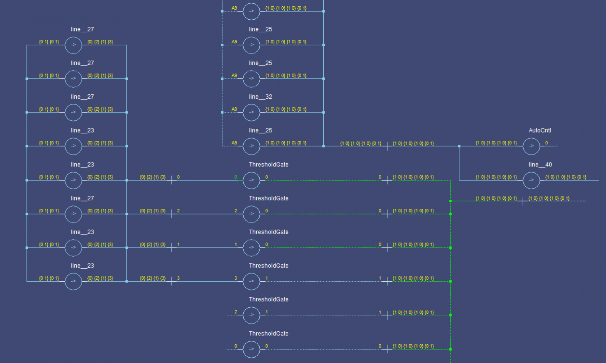
My naming conventions have probably been misleading. I have mostly treated NCL bits as three-state logic (NULL, DATA0, and DATA1) this is a valid way to work with the data, but it is limiting. The better way to think of it is as individual 2-state logic lines (NULL and DATA).
Internally to a component, using single-rail signals is very helpful. Not only are single-rail signals the inputs to all NCL gates, but they can be used as links between components as well. Single-rail signals cannot really be passed through registers because they have to be asserted for the DATA wave to read as complete. This would prevent the signal from conveying meaning, as it would always have the same value during computations.
My Theory
This section is unverified theory. Please share your thoughts below.
I will b using _ to refer to a non-asserted rail (null) and ^ to refer to an asserted rail (data).
Another benefit of this view is that you get more flexibility in state encodings. Standard encodings (that I’ve come across) use mutually exclusive data lines. So a 3-rail signal would have 3 possible states and a 4-rail signal would have 4 states. By thinking of the data more in terms of DATA and NULL, you get to design your own state encodings. For example, with a 4-rail encoding, you could use the following 6 states: {__^^, _^_^, _^^_, ^__^, ^_^_, ^^__}.
State Space Restrictions
A state space is the set of valid states. We will use it here a little more specifically to refer to the valid DATA states. Not all state spaces will actually work for NCL, The completion logic has to be able to correctly identify completed states. For example, if we try to use the following for a 3-rail signal, we have a problem: {__^, _^^, ^^^}. If the result is the last state (^^^) and the data on line 0 arrives first, the completion logic will see it as a complete __^ and pass on the wrong result.
For any state, it has to be able to partially arrive, without looking like another state. This is required for delay insensitivity. A simple way to make this happen is to use M-hot states. By that I mean that each state will have the same number of rails asserted as data (^), and all such states can be used. The number of states in such an assignment for a N-rail signal is M Choose N or C(M, N). This has its maximum value when M=N/2. It also has the benefit that any incomplete state has at most M-1 rails set, which will never match another state.
The logic proof-y version: ∀x,y∈S:(x&y!=x) and (x&y!=y) must hold (& is the bitwise AND operator) where S is the state space.
Using this N/2-hot encoding, the states/rail is
| Rails | States | State Increase Factor |
|---|---|---|
| 1 | 1 | |
| 2 | 2 | 2 |
| 3 | 3 | 1.5 |
| 4 | 6 | 2 |
| 5 | 10 | 1.6667 |
| 6 | 20 | 2 |
Using this encoding, you get nearly twice as many states for each rail you add. Using mutually-exclusive rails (1-hot) you get 1 extra state per rail. Even if you break it up into 2-rail pairs and use combinations of those values, you only double your state space for every 2 rails you add. In the table above, s you increase the number of rails, the factor approaches 2 for the odd numbers of rails as well.
In special cases, you might want a more complex encoding, some examples of valid state spaces:
{___^, ^_^_, _^__}{__^^, ^___, _^__}{^^^_, ^^_^, ^_^^, _^^^}{^^^_, ___^}{__^^, _^_^, _^^_, ^__^, ^_^_, ^^__}
Takeaway
While you can increase the compatibility of your modules by using a standard state space, sometimes you can reduce the number of rails by using more dense encodings. Additionally, signals that exist only between registers (are not passed on) can actually be 1-rail signals, which is something I have a hard time remembering when integrating components. These 1-rail signals can act as enable signals: They can be used to prevent data from propagating, or to allow it to propagate (remember steering).

