I want to start in on some sequential logic. We have a few combinational modules that we can build on already, so the est thing would be to make a sequential-only circuit. Once we’ve clarified how the concept works, we can add in combinational logic in.
By ‘sequential-only’, I am referring to a setup with only registers, it just passes it’s initial input in a loop forever, not changing it. I’m hoping it’ll help me with the concept a bit more, and flush out any issues with the registers.
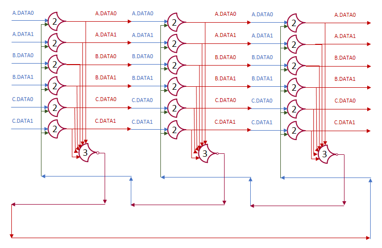
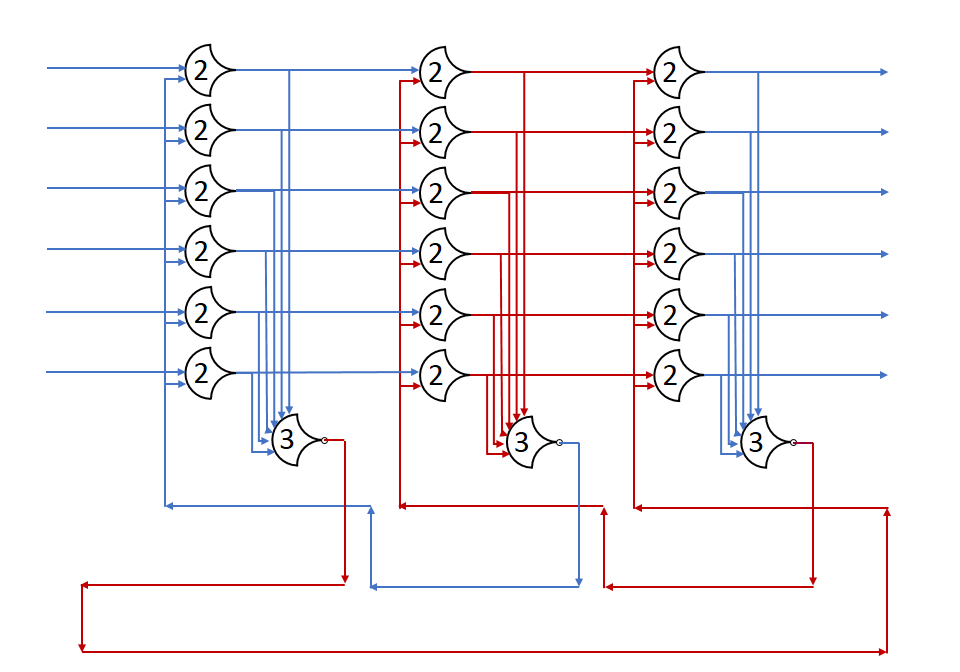
Here’s a diagram of a three stage loop, just imagine the outputs loop back (drawing it would be messy):
Runtime Behavior
Let the initial state of the first stage’s outputs be DATA, with the first stage requesting NULL. The second and third stages are outputting NULL, and requesting DATA. Now let red be DATA, and blue be NULL.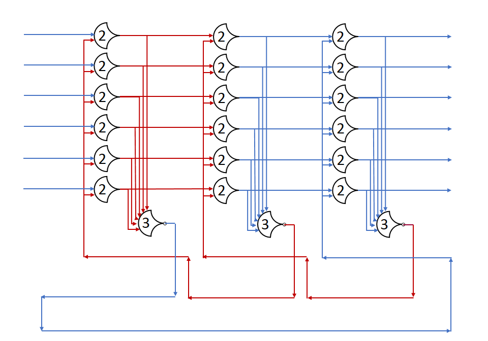
After the gate delay for the register, the DATA wave is passed, and a request for NULL is sent back.
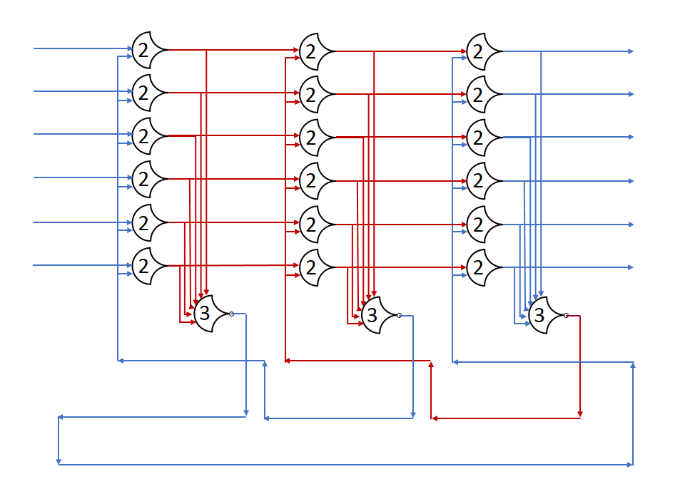
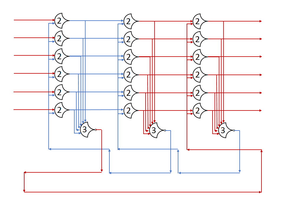
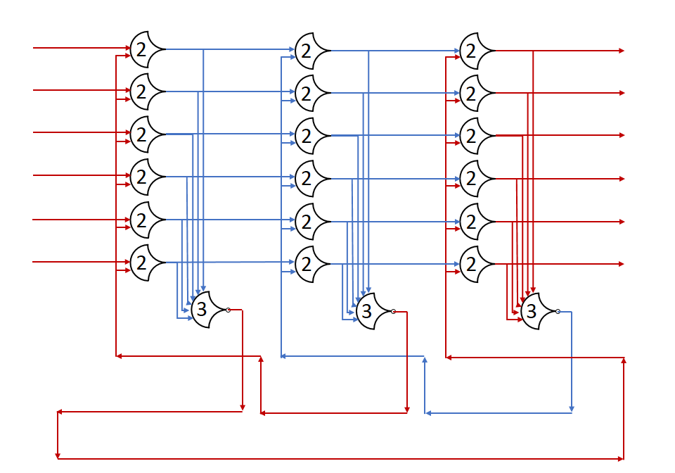
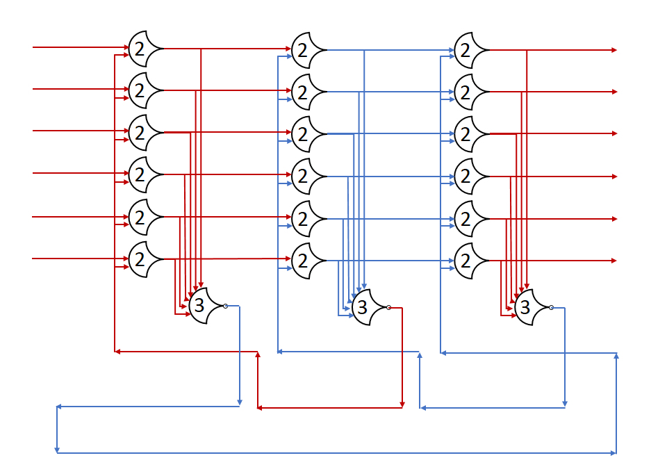
And, we’re back where we started

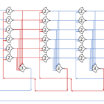
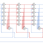
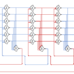
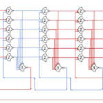
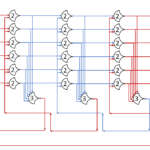
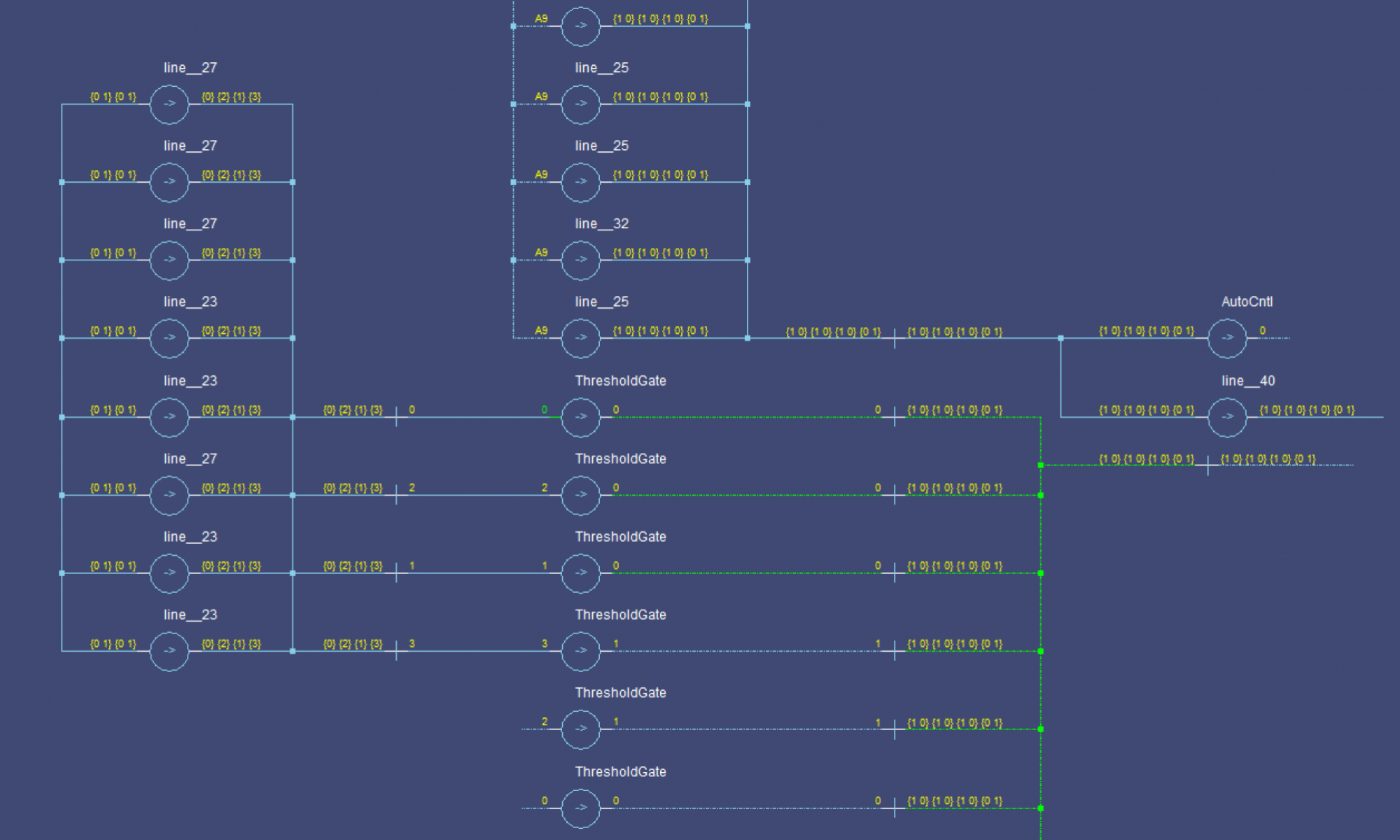
The ring will continue indefinitely. The VHDL source is available here, though without the test script, all stages remain at NULL, requesting DATA. I simulated this, and t turns out that it’s harder to see the pattern in graph form. To make things easier, I raised the number of stages.
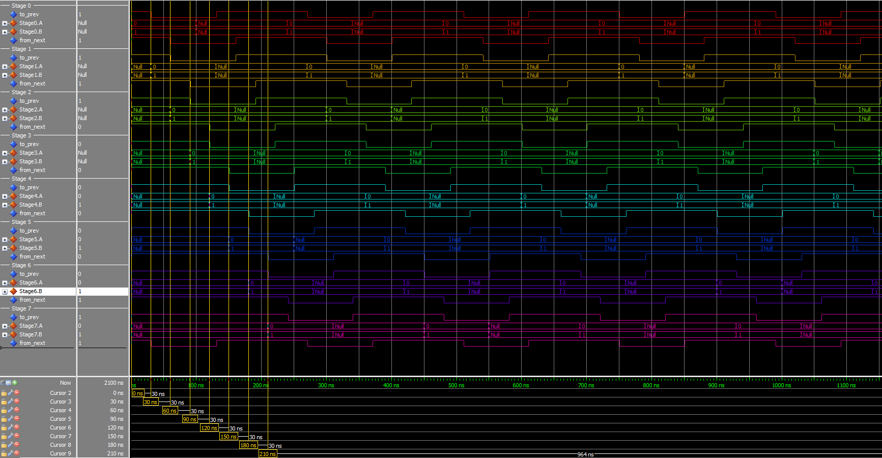
At 8 stages, I start to be able to see it clearly as distinct wavefronts going through the pipeline. To make it really obvious, ramp it up to 12.
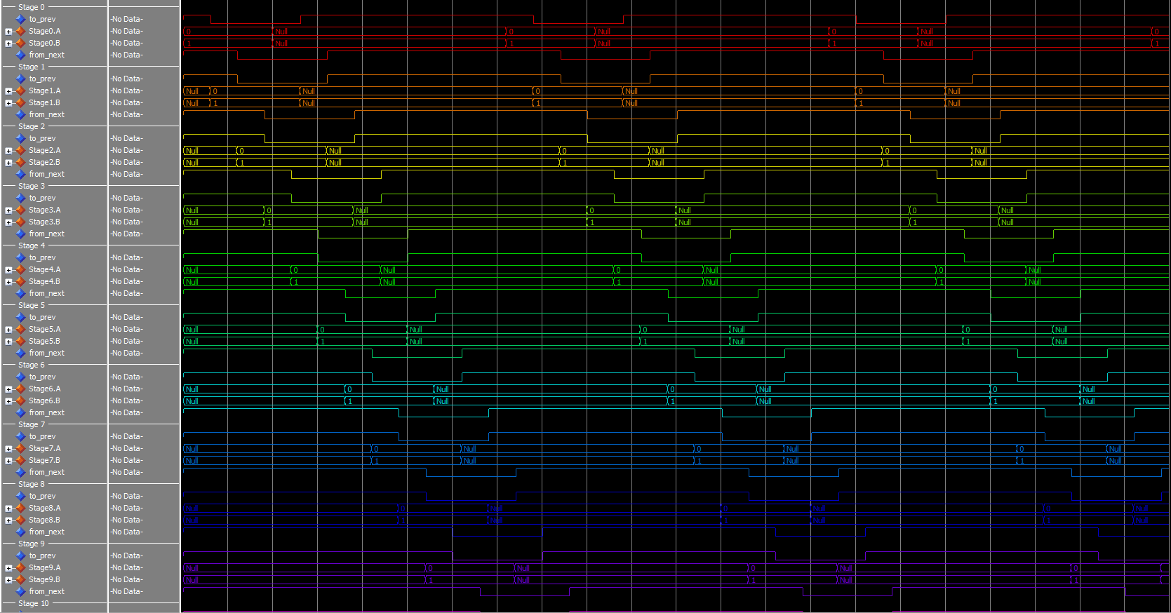
Not all stages shown.
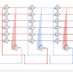
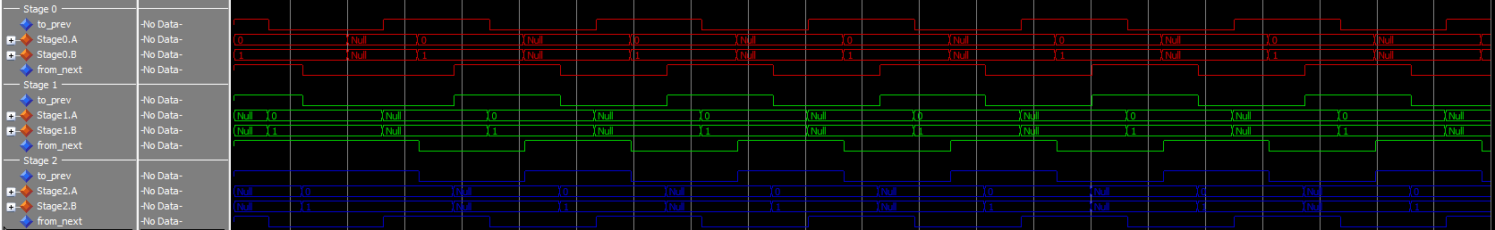
And finally, if set at three, the pattern is harder to see, but it’s there. In the 3-stage case, the time spent requesting NULL and requesting DATA is the same for each stage.
If you use 2 stages, the system locks. A slideshow version of the ring pictures from above. As you can see, the transition to NULL only occurs while there are 2 DATA stages, and the transition to DATA only occurs while there are 2 NULL stages. This is so that no wavefront is ever ‘overwritten’. The second instance of that state saves the value.