Now that we’ve covered making data flow in circles, let’s use that to make a closed-system 4-bit counter. The module will have 4 state bits and 5 outputs (sum & carry out). To do this we’ll need an adder. I have a ripple carry NCL adder here.
We are going to put the adder between two registers, with a third register going back to hold the state during the NULL wavefront.
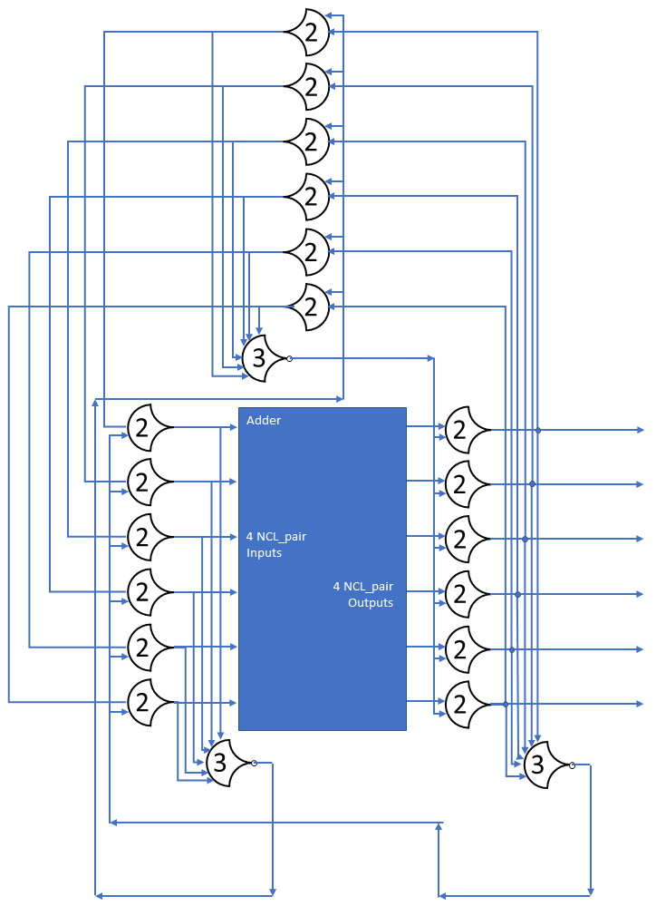
The circuit shown is for a 3-bit adder, just to save space. The concept is the same, just add a bit to each register. Additionally, the adder has a static “0001” input for the B operand, which clears to NULL when the A input goes to NULL, this could be synthesized as the lines that get asserted being gated with TH22 gates with the watcher gate output (non-inverted) being the second input.
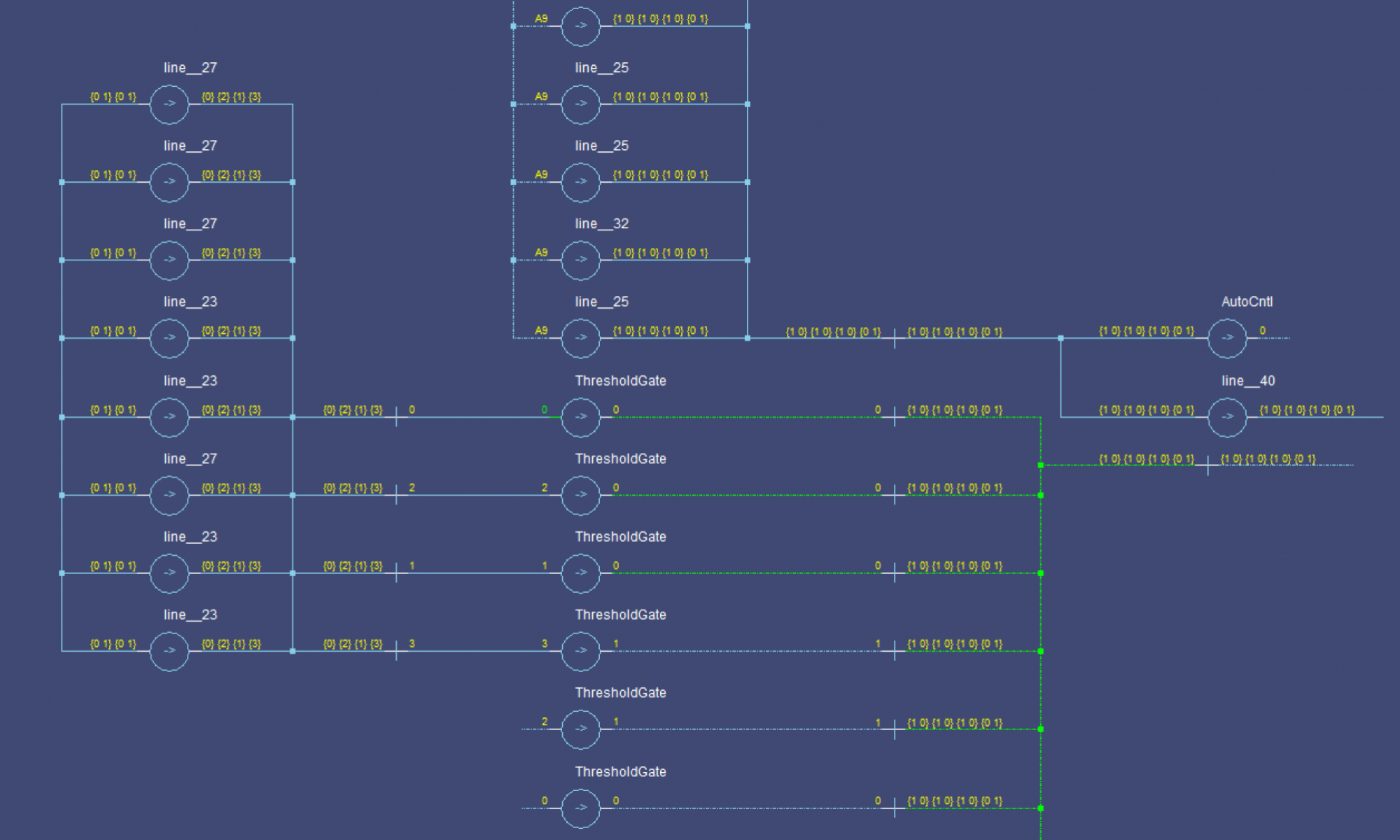
The source for this can be found here, and the simulation script here. Below is a simulation of the circuit. The first rows are the output, the next 3 sets are the registers.
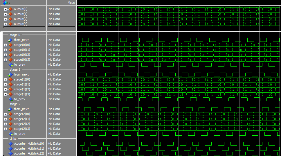
The output cycles from 0 to 15, then resets to 0. During the reset cycle, the Adder’s Carry Out bit is set.
Conclusion
This is a pretty simple sequential circuit, but it demonstrates how to properly feed back the data. The third register is needed because the ‘business logic’ has to be able to go to NULL, without the whole thing losing state.
Commit: 5854b0c